In 1966, Charles Kao and George Hockham published a paper that would transform global communications. Working at Standard Telecommunication Laboratories in England, they proposed that the fundamental limitation of optical fibers was not the glass itself, but impurities that could be removed. If attenuation could be reduced below 20 decibels per kilometer, they argued, fiber optics would become a practical communication medium.
The physics community was skeptical. Existing glass fibers lost 1,000 dB per kilometer—essentially blocking any useful signal after a few meters. But Kao persisted, and in 1970, researchers at Corning Glass Works achieved his target: a fiber with 17 dB/km attenuation using titanium-doped silica. By 1988, the first transatlantic fiber optic cable, TAT-8, entered service. Today, fiber optic cables carry over 99% of intercontinental data traffic, with modern systems achieving speeds exceeding 400 terabits per second on a single fiber.
The Physics of Light Trapping
At its core, fiber optic transmission relies on a phenomenon that seems almost paradoxical: keeping light confined in a material it wants to escape. This is achieved through total internal reflection, a consequence of Snell’s law that governs how light bends when crossing between materials.
When light travels from a medium with higher refractive index to one with lower refractive index—such as from glass to air—it bends away from the perpendicular to the surface. As the angle of incidence increases, the refracted ray bends further until it reaches 90 degrees. Beyond this critical angle, no refraction occurs. The light reflects entirely back into the denser medium.
The critical angle is determined by:
$$\theta_c = \arcsin\left(\frac{n_2}{n_1}\right)$$where $n_1$ is the refractive index of the core and $n_2$ is that of the cladding. For a typical single-mode fiber with a core index of 1.4475 and cladding index of 1.444, the critical angle is approximately 85.9 degrees from the normal. Light hitting the core-cladding boundary at steeper angles is completely trapped.
This trapping creates a light pipe. But not all light can enter the fiber successfully. The numerical aperture defines the acceptance cone—the range of angles at which light can be coupled into the fiber:
$$NA = \sqrt{n_{core}^2 - n_{clad}^2}$$For the fiber described above, NA ≈ 0.10, meaning light must enter within about 5.7 degrees of the fiber axis to propagate.
Anatomy of an Optical Fiber
A standard telecommunications fiber consists of three concentric layers, each serving a distinct purpose.
The core carries the light signal. In single-mode fibers designed for long-distance transmission, the core diameter is 8-10 micrometers—about one-tenth the width of a human hair. This tiny size ensures only one propagation mode, eliminating modal dispersion that would otherwise spread pulses over distance. Multi-mode fibers, used for shorter distances, have cores of 50 or 62.5 micrometers.
The cladding surrounds the core with a slightly lower refractive index. Standard cladding diameter is 125 micrometers, providing the optical boundary for total internal reflection. The refractive index difference between core and cladding is typically less than 1%, making modern fibers “weakly guiding.”
The coating protects the glass from physical damage and moisture. Primary coatings are soft acrylates applied directly during fiber drawing, bringing the diameter to 250 micrometers. Secondary buffer tubes and strength members are added during cabling for mechanical protection.

Image source: Wikipedia - Single-mode optical fiber
The Wavelength Windows
Silica glass has specific wavelength windows where attenuation reaches local minima, making these regions optimal for transmission.
The first window centers around 850 nm, where early fiber systems operated. Attenuation here is relatively high at 2-3 dB/km, limiting practical distances. This wavelength remains common in short-reach multi-mode applications like data center interconnects.
The second window at 1310 nm offers significantly lower attenuation, approximately 0.35 dB/km. More importantly, this wavelength exhibits zero chromatic dispersion in standard fiber, meaning pulses maintain their shape over distance. Many metropolitan networks still use 1310 nm transmission.
The third window around 1550 nm represents the sweet spot for long-distance transmission. Attenuation reaches its minimum of approximately 0.2 dB/km—meaning light can travel 15 kilometers before losing half its power. This wavelength window coincides with the amplification band of erbium-doped fiber amplifiers, making it the default choice for submarine and long-haul terrestrial systems.

Image source: Wikipedia - Optical fiber
Multiplying Capacity: Wavelength Division Multiplexing
The most transformative advancement in fiber optic capacity wasn’t faster lasers or better fibers—it was the realization that multiple wavelengths could travel simultaneously through a single fiber, each carrying independent data streams.
Wavelength Division Multiplexing (WDM) works on the same principle as a prism splitting white light into colors. At the transmitter, multiple laser sources emit at slightly different wavelengths, which are combined and launched into the fiber. At the receiver, a demultiplexer separates the wavelengths back into individual channels.
Coarse WDM (CWDM) spaces channels 20 nm apart, providing up to 18 channels across the full fiber spectrum. This approach suits metropolitan networks where cost matters more than maximum capacity.
Dense WDM (DWDM) squeezes channels much tighter—typically 0.8 nm or even 0.4 nm apart. Modern systems support 80 or more channels in the C-band alone, and when extended across C, L, and S bands, can exceed 150 channels per fiber. With each channel carrying 100 Gbit/s, aggregate capacities surpass 15 Tbit/s on a single fiber.
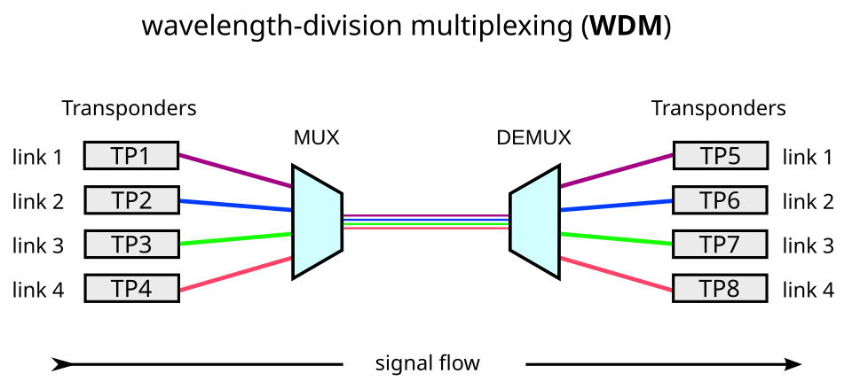
Image source: Wikipedia - Wavelength-division multiplexing
The Amplification Revolution
Before 1987, fiber optic signals required conversion to electrical form every 40-80 kilometers for regeneration. Repeaters detected the weakened optical signal, converted it to electrical pulses, cleaned up the timing, and retransmitted as light. This process was expensive, complex, and limited by the electronics at each station.
The erbium-doped fiber amplifier changed everything. Developed independently by teams at the University of Southampton and Bell Labs in 1986-87, EDFA amplifies optical signals directly, without conversion to electrical form.
The mechanism exploits the quantum properties of erbium ions embedded in the fiber core. When pumped with 980 nm or 1480 nm light, erbium ions absorb energy and transition to an excited state. Incoming signal photons at 1550 nm trigger stimulated emission, causing the excited ions to release their energy as additional photons at exactly the signal wavelength—amplifying the signal while preserving its phase and direction.
A typical EDFA provides 20-40 dB of gain across the C-band, amplifying all WDM channels simultaneously. More critically, it operates transparently to data rate and modulation format. A system upgraded from 10 Gbit/s to 100 Gbit/s requires no changes to the amplifiers along the route.

Image source: Wikipedia - Optical amplifier
Conquering the Oceans
Submarine cables represent the most demanding application of fiber optic technology. These systems must operate reliably for 25 years at depths exceeding 8,000 meters, with no possibility of maintenance.
A typical submarine cable contains 4-12 fiber pairs encased in multiple protective layers. Steel armor wires provide tensile strength for laying and recovery operations. A copper conductor carries high-voltage DC power to the repeaters—typically 10,000-15,000 volts at each end, with the cable acting as a virtual ground at the midpoint. The entire assembly is sheathed in polyethylene for water resistance.
Repeaters are spaced every 50-100 kilometers, each housing EDFA amplifiers for every fiber pair. A 10,000-kilometer transpacific cable contains over 100 repeaters, each of which must operate flawlessly for the system’s lifetime.

Image source: Wikipedia - Submarine communications cable
TAT-8, the first transatlantic fiber cable, entered service in December 1988 carrying 280 Mbit/s on two fiber pairs. Modern transatlantic cables exceed 200 Tbit/s—a 700,000-fold increase in just 36 years.
Modern Modulation: Beyond Simple Pulses
Early fiber systems used simple on-off keying: a light pulse represented a “1,” absence of light a “0.” But as data rates pushed beyond 10 Gbit/s, this approach hit fundamental limits from chromatic dispersion and polarization mode dispersion.
Coherent detection, borrowed from radio communications, transformed what was possible. By transmitting not just amplitude but also phase information, coherent systems encode multiple bits per symbol. Dual-polarization quadrature phase-shift keying (DP-QPSK) encodes 4 bits per symbol. DP-16QAM increases this to 8 bits per symbol.
The receiver mixes the incoming signal with a local oscillator laser, recovering both amplitude and phase. Digital signal processing then reconstructs the transmitted data, correcting for dispersion, nonlinear effects, and other impairments accumulated over thousands of kilometers.
This sophistication comes at a cost: coherent transceivers require complex DSP ASICs consuming tens of watts. But the payoff is dramatic—a 100 Gbit/s coherent signal travels the same distance as a 10 Gbit/s direct-detect signal, with better spectral efficiency.
Nonlinear Limits
As power levels and distances increase, the fiber itself becomes a nonlinear medium. The Kerr effect causes the refractive index to vary with optical intensity, leading to self-phase modulation, cross-phase modulation, and four-wave mixing.
These effects create trade-offs. Higher launch power extends reach but increases nonlinear penalties. More WDM channels increase capacity but raise cross-talk. Dispersion that was once purely detrimental now serves a purpose: non-zero dispersion-shifted fibers deliberately retain some dispersion to suppress four-wave mixing in WDM systems.
Modern systems optimize across all dimensions—power, dispersion management, modulation format, and symbol rate—to push against these fundamental limits. The record as of 2024 stands at 402 Tbit/s through a single fiber, achieved by packing 1,505 wavelength channels across six bands using specialized multi-core fiber.
The Last Mile and Beyond
While long-haul fiber achieves remarkable performance, the economics differ for residential access. Fiber-to-the-home (FTTH) deployments use passive optical networks, sharing one fiber among 32 or 64 users through optical splitters. The optical line terminal at the central office transmits downstream at 1490 nm; user terminals respond upstream at 1310 nm. A third wavelength at 1550 nm may carry video overlay.
GPON, the dominant standard, provides 2.4 Gbit/s downstream and 1.2 Gbit/s upstream per fiber—sufficient for most residential needs. Next-generation XGS-PON increases this to symmetrical 10 Gbit/s without changing the fiber infrastructure.
The Invisible Infrastructure
Over 5 billion kilometers of optical fiber have been deployed globally. These hair-thin strands of glass, illuminated by lasers and amplified by rare-earth ions, form the backbone of modern civilization. Every streaming video, cloud computation, and video call travels through this network at approximately 200,000 kilometers per second—two-thirds the speed of light in vacuum, delayed only by the refractive index of silica.
The technology that began with Kao’s theoretical insight now carries over 99% of intercontinental data. Satellites, despite their visibility, handle less than 1% of international traffic. The real infrastructure runs beneath the oceans, buried along highways, and threaded through buildings—invisible, unremarked, and absolutely essential.
References
-
Kao, K.C. and Hockham, G.A. (1966). “Dielectric-fibre surface waveguides for optical frequencies.” Proceedings of the Institution of Electrical Engineers, 113(7), 1151-1158.
-
Maurer, R.D. (1973). “Glass fibers for optical communications.” Proceedings of the IEEE, 61(4), 452-462.
-
Desurvire, E., et al. (1987). “High-gain erbium-doped traveling-wave fiber amplifier.” Optics Letters, 12(11), 888-890.
-
Mears, R.J., et al. (1987). “Low-noise erbium-doped fibre amplifier operating at 1.54μm.” Electronics Letters, 23(19), 1026-1028.
-
Agrawal, G.P. (2019). Fiber-Optic Communication Systems. 5th ed. Wiley.
-
Keiser, G. (2015). Optical Fiber Communications. 5th ed. McGraw-Hill Education.
-
Telegeography Submarine Cable Map. Available at: https://www.submarinecablemap.com/
-
Corning Incorporated. (2020). “50 Years of Fiber Innovation.” Technical Publication.