In November 2020, SpaceX requested that the Federal Communications Commission modify its license to operate 348 satellites at an altitude of 560 kilometers with an inclination of 97.6 degrees. These satellites would carry inter-satellite laser links—technology that allows satellites to communicate directly with each other without bouncing signals through ground stations. The physics behind this request reveals something counterintuitive: for long-distance communication, signals traveling through the vacuum of space can arrive faster than signals traveling through fiber optic cables on Earth.
The speed of light in a vacuum is approximately 299,792,458 meters per second—the cosmic speed limit established by Einstein’s special relativity. But light traveling through glass, the medium that carries internet traffic through fiber optic cables, moves roughly 31% slower. This refractive index of approximately 1.47 for silica glass creates a fundamental advantage for satellite communication over long distances, one that becomes more pronounced as the distance increases.
The Mathematics of Propagation Delay
Latency in any communication system stems from two sources: propagation delay and processing delay. Propagation delay is purely a function of distance and signal velocity:
$$t_{propagation} = \frac{d}{v}$$where $d$ is the path length and $v$ is the signal velocity. For fiber optic cables, $v \approx 0.67c$, where $c$ is the speed of light in vacuum. For signals traveling through space, $v = c$.
Consider a signal traveling from New York to London—a distance of approximately 5,567 kilometers as the crow flies. Through fiber optic cables, this signal must traverse approximately 7,000 kilometers of cable due to the non-linear routing of undersea cables. The propagation delay through fiber would be:
$$t_{fiber} = \frac{7,000 \times 10^3}{0.67 \times 3 \times 10^8} \approx 34.8 \text{ ms (one way)}$$Through a low Earth orbit satellite constellation at 550 kilometers altitude, the signal travels approximately 5,800 kilometers through vacuum (up to the satellite, potentially through inter-satellite links, and back down). The propagation delay would be:
$$t_{satellite} = \frac{5,800 \times 10^3}{3 \times 10^8} \approx 19.3 \text{ ms (one way)}$$This represents a theoretical improvement of approximately 15 milliseconds in one-way latency. For round-trip communication, the advantage doubles to roughly 30 milliseconds—a difference imperceptible for web browsing but significant for high-frequency trading, where a 1-millisecond advantage has been estimated to be worth $100 million annually to a major brokerage firm.
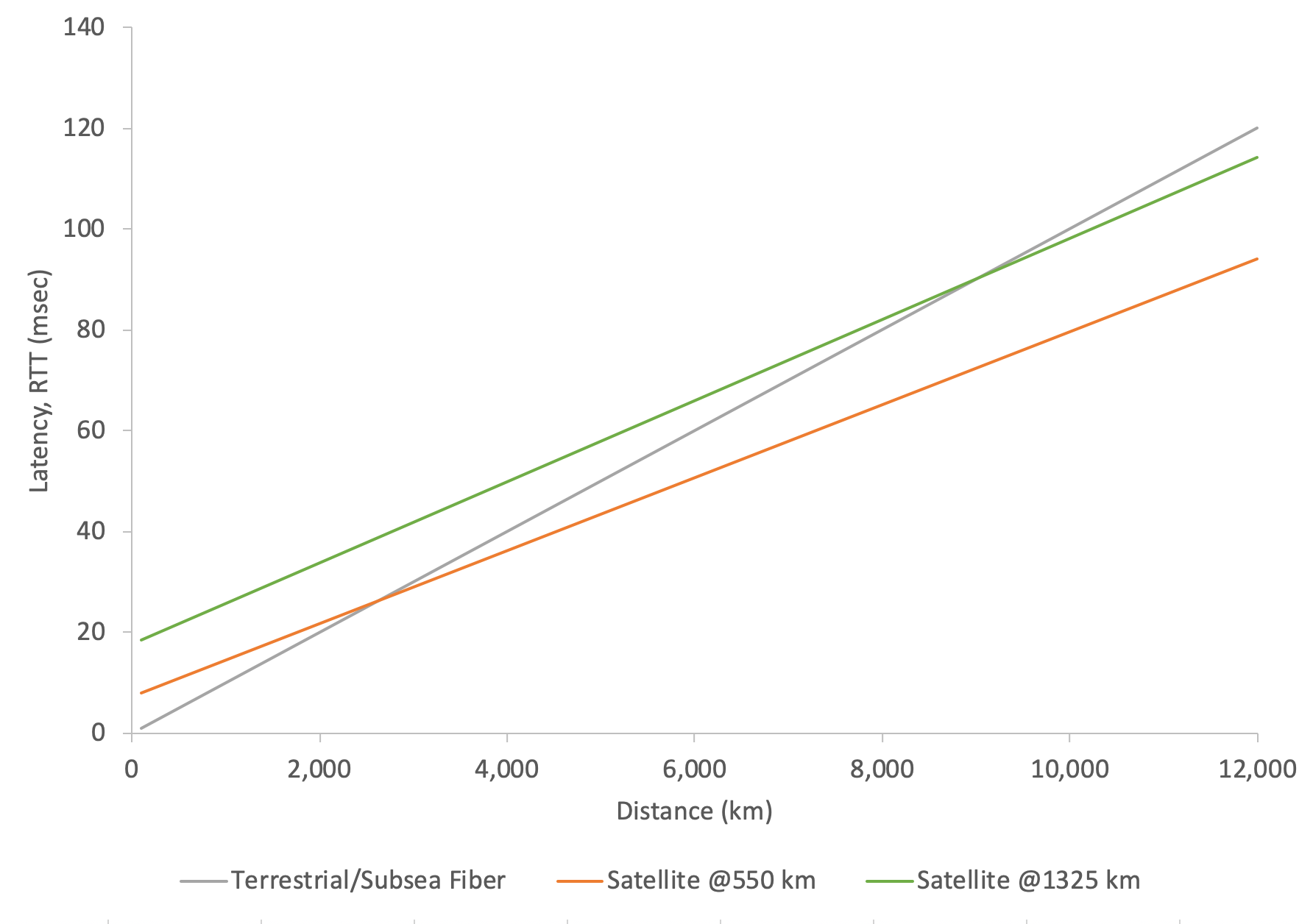
Image source: Frank Rayal - Latency in LEO Satellites vs. Terrestrial Fiber
The crossover distance—the point at which satellite communication becomes faster than fiber—depends on satellite altitude. For satellites at 550 kilometers, this breakeven occurs around 2,700 kilometers of terrestrial distance. For higher orbits at 1,325 kilometers, the breakeven extends to approximately 9,000 kilometers.
The Phased Array Revolution: Steering Without Moving Parts
Traditional satellite dishes rely on mechanical motors to track satellites across the sky. As a satellite passes overhead, the dish must physically rotate to maintain alignment—a slow process unsuitable for tracking multiple fast-moving low Earth orbit satellites. The solution lies in phased array antennas, which steer beams electronically by manipulating the phase of signals across hundreds of individual antenna elements.
A phased array antenna consists of multiple radiating elements, each fed with a signal that has a specific phase relationship to the others. When these signals combine in space, they create constructive interference in the desired direction and destructive interference elsewhere. The direction of the main beam depends on the phase difference between adjacent elements:
$$\theta = \arcsin\left(\frac{\lambda \Delta\phi}{2\pi d}\right)$$where $\theta$ is the beam angle from broadside, $\lambda$ is the wavelength, $\Delta\phi$ is the phase difference between adjacent elements, and $d$ is the element spacing.
graph LR
    subgraph "Phased Array Beam Steering"
        A[Signal Source] --> B[Phase Shifter 1]
        A --> C[Phase Shifter 2]
        A --> D[Phase Shifter 3]
        A --> E[Phase Shifter 4]
        B --> F[Antenna 1]
        C --> G[Antenna 2]
        D --> H[Antenna 3]
        E --> I[Antenna 4]
        F --> J[Combined Beam<br/>Direction: θ]
        G --> J
        H --> J
        I --> J
    end
Modern satellite internet user terminals contain approximately 1,280 individual antenna elements arranged in a hexagonal pattern. Each element can have its phase adjusted independently, allowing the antenna to track satellites across a 110-degree field of view without any mechanical movement. Phase adjustments occur in nanoseconds, enabling the terminal to switch between satellites in milliseconds as one disappears below the horizon and another rises.
The antenna gain of a phased array is directly proportional to the number of elements:
$$G \approx N \cdot G_e$$where $N$ is the number of elements and $G_e$ is the gain of each element. This relationship explains why larger arrays provide better performance—they concentrate more energy in the desired direction and reject interference more effectively.
Inter-Satellite Laser Links: The Backbone of Global Coverage
The third generation of low Earth orbit satellites introduced optical inter-satellite links—laser communication terminals that allow satellites to exchange data without ground station involvement. Each satellite carries three such terminals operating at data rates up to 200 gigabits per second.
Laser communication in space offers several advantages over radio frequency links. First, the extremely high carrier frequency—approximately 200 terahertz for near-infrared lasers—enables enormous bandwidth. Second, the narrow beam divergence of laser light (typically a few microradians) concentrates energy efficiently and minimizes interference with other satellites.
The physics of free-space optical communication follows the Friis transmission equation adapted for optical wavelengths. The received optical power depends on transmitted power, telescope apertures, distance, and atmospheric conditions:
$$P_r = P_t \cdot \eta_t \cdot \eta_r \cdot \left(\frac{D_r}{D_t + \theta \cdot L}\right)^2 \cdot e^{-\alpha L}$$where $P_r$ is received power, $P_t$ is transmitted power, $\eta_t$ and $\eta_r$ are transmitter and receiver efficiencies, $D_r$ and $D_t$ are receiver and transmitter aperture diameters, $\theta$ is beam divergence, $L$ is link distance, and $\alpha$ is atmospheric attenuation coefficient.
In the vacuum of space, $\alpha \approx 0$, allowing links to span thousands of kilometers with minimal power. The mini laser terminals achieve 25 gigabits per second over distances up to 4,000 kilometers, enabling satellites to relay data across oceans without any ground infrastructure.
The Doppler Challenge: When Satellites Move Too Fast
Low Earth orbit satellites travel at approximately 7.8 kilometers per second—fast enough to circle the Earth in roughly 90 minutes. This velocity creates a significant Doppler shift in radio signals, a phenomenon that must be actively compensated for communication to succeed.
The Doppler shift for a satellite moving directly toward or away from a ground station is:
$$\Delta f = f_0 \cdot \frac{v}{c}$$where $f_0$ is the transmitted frequency, $v$ is the relative velocity, and $c$ is the speed of light. For a satellite transmitting at 12 gigahertz (Ku-band) and moving at 7.8 km/s, the maximum Doppler shift approaches:
$$\Delta f = 12 \times 10^9 \cdot \frac{7,800}{3 \times 10^8} \approx 312 \text{ kHz}$$This shift varies continuously as the satellite passes overhead—from maximum positive shift during approach, through zero at closest approach, to maximum negative shift during recession. Over the course of a 10-minute pass, the frequency changes by more than 600 kilohertz.
Modern satellite communication systems compensate for Doppler shift through predictive modeling. Ground stations calculate the expected frequency offset based on satellite orbital parameters and adjust receiver tuning accordingly. For user terminals, this compensation happens automatically—the terminal continuously tracks the satellite and adjusts its frequency reference to maintain lock.
Frequency Bands: The Spectrum Trade-Off
Satellite internet systems operate primarily in Ku-band (12-18 GHz) and Ka-band (26.5-40 GHz). Each band represents a trade-off between available bandwidth and susceptibility to atmospheric effects.
Higher frequencies offer more bandwidth—Ka-band can deliver significantly higher data rates than Ku-band—but they also suffer greater attenuation from rain. The physics of rain attenuation relates to the relationship between raindrop size and wavelength:
$$A = aR^b \cdot L$$where $A$ is attenuation in decibels, $R$ is rain rate, $L$ is path length through rain, and $a$ and $b$ are frequency-dependent coefficients. At 12 GHz (Ku-band), heavy rain might cause 1-2 dB/km of attenuation. At 30 GHz (Ka-band), the same rain could cause 5-8 dB/km.
This increased susceptibility to weather has driven the development of adaptive coding and modulation schemes. When rain is detected, the system automatically reduces the modulation order and increases error correction overhead, trading throughput for reliability. When conditions improve, the system shifts back to more spectrally efficient modes.

Image source: ReliaSat - Ku, K, and Ka Bands in LEO Satellites
The Atmospheric Window: Where Signals Survive
Not all frequencies can penetrate Earth’s atmosphere. Radio waves below about 30 MHz are reflected by the ionosphere. Above about 300 GHz, atmospheric gases—particularly water vapor and oxygen—absorb radiation strongly. The frequencies between these limits form “windows” through which satellite communication is possible.
The primary absorption features are the water vapor absorption line at 22.2 GHz and the oxygen absorption complex near 60 GHz. These features create natural boundaries between frequency bands and explain why Ka-band (26.5-40 GHz) sits above the water vapor line while Ku-band (12-18 GHz) sits below it.
For satellite internet systems, this atmospheric physics dictates operational constraints. Systems operating near absorption lines must budget for additional path loss. Systems in regions with heavy rainfall must account for rain fade margins in their link budgets. The most successful systems operate in frequency ranges that balance these atmospheric effects against bandwidth availability.
Why This Matters
The convergence of these technologies—phased array antennas for rapid tracking, inter-satellite laser links for global routing, sophisticated Doppler compensation for fast-moving platforms, and optimized frequency selection for atmospheric penetration—has enabled a new paradigm in global connectivity. Satellite internet is no longer a last-resort option for remote locations; it is becoming a competitive alternative for latency-sensitive applications.
The physics that makes this possible is the same physics that governs all electromagnetic communication. What has changed is the engineering: the ability to pack thousands of antenna elements into a flat panel, the precision to maintain laser links between satellites traveling at 28,000 kilometers per hour, and the computational power to predict and compensate for orbital dynamics in real time.
As satellite constellations grow to tens of thousands of spacecraft, the fundamental physics remains unchanged. Light still travels at $c$ in vacuum. Refractive index still slows signals in fiber. Doppler shift still affects moving transmitters. But our ability to engineer systems that work within these constraints—sometimes turning apparent disadvantages into advantages—continues to advance.
References
-
Chaudhry, A. T., & Yanikomeroglu, H. (2021). “Laser Inter-Satellite Links in a Starlink Constellation.” arXiv preprint arXiv:2103.00056.
-
Rayal, F. (2021). “Latency in LEO Satellites vs. Terrestrial Fiber.” Frank Rayal Research.
-
Delos, P., Broughton, B., & Jonsson, J. (2019). “Phased Array Beamforming ICs Simplify Antenna Design.” Analog Dialogue, 53(1).
-
European Space Agency. “Satellite Frequency Bands.” ESA Applications.
-
Starlink. (2025). “Technology Overview.” SpaceX Corporation.
-
ITU-R. “Recommendation P.618: Propagation Data and Prediction Methods Required for the Design of Earth-Space Telecommunication Systems.”
-
National Telecommunications and Information Administration. “United States Frequency Allocation Chart.”
-
SatelliteGroundStation.com. (2026). “Doppler Shift Explained and How Stations Compensate.”
-
MDPI Sensors. (2021). “A Survey of Rain Fade Models for Earth–Space Telecommunication Links.”
-
Brodkin, J. (2021). “SpaceX adds laser links to Starlink satellites to serve Earth’s polar areas.” Ars Technica.