The coffee shop has free Wi-Fi. The password is posted on a chalkboard near the counter. You sit in the corner booth, open your laptop, and connect. The signal passes through three walls, a glass window, and a wooden partition before reaching your device. How?
This isn’t a minor engineering achievement. Your router is broadcasting radio waves at frequencies measured in billions of cycles per second, encoding gigabytes of data into invisible electromagnetic fields, and somehow that signal arrives intact after bouncing off your refrigerator, penetrating your walls, and competing with your neighbor’s network. Understanding how this works requires peeling back layers of physics that most people never consider—electromagnetic wave behavior, material properties, and the mathematical cleverness of modern encoding schemes.
Radio Waves Are Just Light You Can’t See
Wi-Fi operates on the same fundamental principle as visible light: electromagnetic radiation. The difference is purely one of frequency. While visible light oscillates at roughly 400 to 790 terahertz (trillions of cycles per second), Wi-Fi uses 2.4 gigahertz or 5 gigahertz (billions of cycles per second). Both are photons traveling at the speed of light, carrying energy through space.
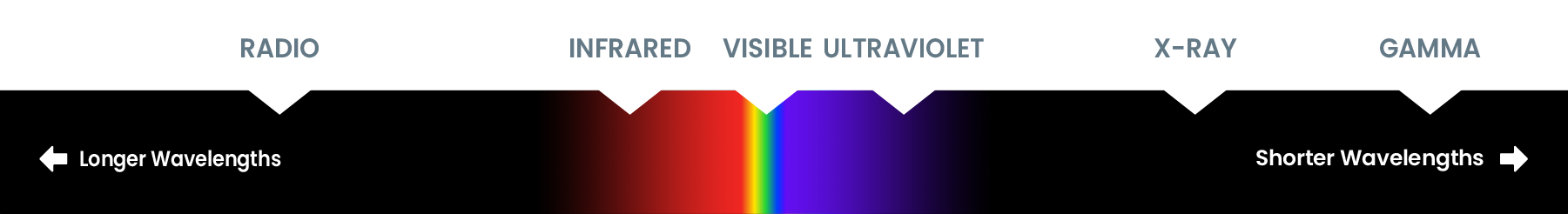
Image source: NASA Science
The electromagnetic spectrum spans from radio waves with wavelengths measured in kilometers to gamma rays with wavelengths smaller than atomic nuclei. Wi-Fi’s 2.4 GHz signals have a wavelength of approximately 12.5 centimeters (about 5 inches), while 5 GHz signals have a wavelength of about 6 centimeters (roughly 2.4 inches). This wavelength difference turns out to be enormously consequential.
When an alternating electric current flows through your router’s antenna, it creates oscillating electric and magnetic fields that propagate outward. These fields form an electromagnetic wave—a self-sustaining disturbance that carries energy through space. The antenna’s job is to efficiently convert electrical energy into this radiating electromagnetic field, and your device’s antenna does the reverse, converting the field back into electrical signals.
Why Walls Are Semi-Transparent to Radio Waves
The question of penetration comes down to how electromagnetic waves interact with matter. When a wave encounters a material, three things can happen: it can be transmitted (pass through), absorbed (its energy converted to heat), or reflected (bounce off). The proportions depend on the wave’s frequency and the material’s properties.
Radio waves, including Wi-Fi frequencies, interact primarily with the electrons in materials. In conductors like metal, electrons move freely and readily absorb and re-radiate the wave’s energy, which is why a metal sheet blocks Wi-Fi completely. In insulators like wood, drywall, or glass, electrons are more tightly bound to their atoms. The oscillating electric field of the radio wave causes these bound electrons to vibrate slightly, but they don’t absorb the wave’s energy efficiently. The wave passes through with only partial attenuation.
This is similar to why glass is transparent to visible light—the electrons in glass don’t have energy levels matching the energy of visible light photons, so the light passes through. Different frequencies interact differently with the same material. Your microwave oven operates at 2.45 GHz—nearly identical to 2.4 GHz Wi-Fi—but water molecules in food absorb this frequency extremely efficiently because their molecular rotation modes match this energy. That’s why microwaves heat food, but Wi-Fi doesn’t.
The Numbers: How Much Signal Loss?
The US National Institute of Standards and Technology (NIST) conducted extensive measurements of signal attenuation through common building materials. Their findings, published in “Electromagnetic Signal Attenuation in Construction Materials,” provide concrete numbers for 5 GHz signals:
| Material | Attenuation (dB) |
|---|---|
| Drywall | ~0 dB |
| Plywood | ~0 dB |
| Glass | 0.07 dB |
| Timber | 3.28 dB |
| Brick | 15.28 dB |
| Masonry block | 14.93 dB |
| Concrete (102mm) | 26.00 dB |
| Concrete (203mm) | 55.16 dB |
| Reinforced concrete | 53.80 dB |
A decibel (dB) is a logarithmic measure of power ratio. A 3 dB loss means half the power is lost; 10 dB means 90% is lost; 20 dB means 99% is lost. That 55 dB attenuation through 8-inch concrete? That’s roughly 99.9997% of the signal absorbed. The numbers explain why concrete walls are Wi-Fi’s nemesis while drywall might as well be invisible.
xychart-beta
    title "Wi-Fi Signal Attenuation by Material (5 GHz)"
    x-axis ["Drywall", "Plywood", "Glass", "Timber", "Brick", "Masonry", "Concrete 102mm", "Concrete 203mm", "Reinforced Concrete"]
    y-axis "Attenuation (dB)" 0 --> 60
    bar [0, 0, 0.07, 3.28, 15.28, 14.93, 26, 55.16, 53.8]
The 2.4 GHz vs. 5 GHz Trade-off
Modern routers typically offer both frequency bands, and understanding the physics reveals why neither is universally superior.
Lower frequency waves have longer wavelengths, which means they diffract (bend around obstacles) more effectively. Diffraction occurs when a wave encounters an edge or obstacle—the wave “spreads out” into the shadow region behind the obstacle. The amount of diffraction depends on the ratio of wavelength to obstacle size. A 12.5 cm wavelength (2.4 GHz) diffracts more readily around typical obstacles than a 6 cm wavelength (5 GHz).
Additionally, longer wavelengths penetrate materials slightly better because they have lower energy per photon and interact less strongly with the electrons in materials. This is why 2.4 GHz signals typically provide better range and wall penetration than 5 GHz.
However, 5 GHz offers significant advantages. Higher frequency means more available bandwidth—the range of frequencies you can use for transmitting data. The 2.4 GHz band offers about 80 MHz of total spectrum, divided into channels. The 5 GHz band offers up to 500 MHz or more, depending on your regulatory domain. More bandwidth means more data capacity.
Furthermore, 5 GHz is less crowded. Microwave ovens, Bluetooth devices, cordless phones, and countless other consumer electronics share the 2.4 GHz band. The 5 GHz band has fewer interferers and more non-overlapping channels, reducing congestion.
quadrantChart
    title "Wi-Fi Frequency Band Trade-offs"
    x-axis "Lower Bandwidth --> Higher Bandwidth"
    y-axis "Worse Penetration --> Better Penetration"
    quadrant-1 "High Speed, Good Range"
    quadrant-2 "Lower Speed, Good Range"
    quadrant-3 "Lower Speed, Poor Range"
    quadrant-4 "High Speed, Poor Range"
    "2.4 GHz": [0.2, 0.8]
    "5 GHz": [0.8, 0.3]
    "6 GHz (Wi-Fi 6E/7)": [0.95, 0.15]
How Data Rides on Radio Waves
Getting a radio wave to propagate through space is one challenge. Encoding meaningful data onto it is another. Wi-Fi uses a sophisticated modulation scheme called Orthogonal Frequency Division Multiplexing (OFDM).
Rather than sending data on a single carrier frequency, OFDM divides the signal across multiple subcarriers—52 data subcarriers in 802.11a/g/n/ac. These subcarriers are “orthogonal” to each other, meaning they’re spaced precisely so they don’t interfere despite overlapping in frequency. This orthogonality is achieved by spacing subcarriers at intervals of $1/T$, where $T$ is the symbol duration.
Each subcarrier is modulated using Quadrature Amplitude Modulation (QAM), which encodes data by varying both the amplitude and phase of the carrier wave. 64-QAM encodes 6 bits per symbol, 256-QAM encodes 8 bits, and 1024-QAM (introduced in Wi-Fi 6) encodes 10 bits. The trade-off is that higher-order QAM requires a cleaner signal—more noise or interference means more decoding errors.
The brilliance of OFDM lies in how it handles multipath propagation. In real environments, signals bounce off walls, furniture, and other surfaces, arriving at the receiver via multiple paths of different lengths. This creates interference patterns that can severely degrade single-carrier signals. OFDM’s subcarriers are narrow enough that multipath-induced distortion is minimal per subcarrier, and a “cyclic prefix”—a copy of the end of each symbol appended to the beginning—allows the receiver to handle delayed copies of the signal gracefully.
The Inverse Square Law and Why Signal Gets Weak
As radio waves propagate outward from an antenna, they spread over an expanding sphere. The power density (power per unit area) decreases with distance according to the inverse square law:
$$I = \frac{P}{4\pi r^2}$$Where $I$ is intensity (power per unit area), $P$ is the radiated power, and $r$ is the distance from the source. Double the distance, quarter the signal strength. This is fundamental physics—not a limitation of antenna design.
In practice, Wi-Fi signal strength is measured in dBm (decibels relative to one milliwatt). A typical router might transmit at +20 dBm (100 mW). At 1 meter, you might receive -30 dBm. At 10 meters, with line of sight, perhaps -50 dBm. Add walls, furniture, and interference, and you might see -70 dBm or worse.
Signal quality matters more than raw strength. The Signal-to-Noise Ratio (SNR) determines how reliably data can be decoded. A -60 dBm signal with -90 dBm noise floor (30 dB SNR) will outperform a -50 dBm signal with -60 dBm noise floor (only 10 dB SNR).
xychart-beta
    title "Signal Strength vs Distance (Line of Sight)"
    x-axis "Distance (meters)" [1, 2, 5, 10, 15, 20, 30, 50]
    y-axis "Signal Strength (dBm)" -90 --> -20
    line [-30, -36, -44, -50, -54, -56, -60, -64]
MIMO: Turning Multipath into an Advantage
Traditional radio systems treated multipath propagation as a problem to overcome. Multiple-Input Multiple-Output (MIMO) technology turned it into an advantage.
A MIMO system uses multiple antennas at both transmitter and receiver. In a 4×4 MIMO configuration, the router has four transmit antennas and your device has four receive antennas. Each transmit antenna sends a different data stream, and the multiple paths through the environment create distinct “channels” between each antenna pair.
The receiver uses sophisticated signal processing to separate these streams, effectively creating multiple parallel data channels in the same frequency bandwidth. The theoretical capacity increase scales with the number of antennas:
$$C = B \cdot \min(N_t, N_r) \cdot \log_2(1 + \text{SNR})$$Where $N_t$ and $N_r$ are the number of transmit and receive antennas respectively. In practice, 4×4 MIMO can roughly quadruple throughput compared to a single-antenna system, assuming sufficient SNR and multipath richness.
flowchart LR
    subgraph TX[Transmitter - 4 Antennas]
        t1[Ant 1]
        t2[Ant 2]
        t3[Ant 3]
        t4[Ant 4]
    end

    subgraph Channel[Wireless Channel - Multipath]
        p1[Path 1]
        p2[Path 2]
        p3[Path 3]
        p4[Path 4]
    end

    subgraph RX[Receiver - 4 Antennas]
        r1[Ant 1]
        r2[Ant 2]
        r3[Ant 3]
        r4[Ant 4]
    end

    t1 --> p1 --> r1
    t2 --> p2 --> r2
    t3 --> p3 --> r3
    t4 --> p4 --> r4
Beamforming: Focusing the Signal
Omnidirectional antennas radiate equally in all directions—great for coverage, wasteful for range. Beamforming directs signal energy toward specific devices.
The principle is straightforward: by controlling the phase and amplitude of signals from multiple antennas, you can create constructive interference in the desired direction and destructive interference elsewhere. It’s like using multiple speakers to focus sound in one spot.
Explicit beamforming, introduced in 802.11n and improved in subsequent standards, involves the receiver sending channel state information back to the transmitter. The transmitter then precodes its signals to optimize transmission toward that specific receiver. This can provide 3-5 dB of gain—enough to noticeably improve range and reliability.
Wi-Fi 6 and Wi-Fi 7: What Changed
The latest Wi-Fi standards brought more than speed improvements.
Wi-Fi 6 (802.11ax) introduced OFDMA (Orthogonal Frequency Division Multiple Access), which extends OFDM by allowing multiple users to share the same OFDM symbol. Different subcarriers can be allocated to different devices simultaneously, rather than each device waiting for a complete transmission opportunity. This dramatically improves efficiency in dense environments.
Target Wake Time (TWT) allows devices to negotiate when they’ll wake up to receive transmissions, reducing power consumption for IoT devices. BSS Coloring reduces interference by allowing devices to distinguish between transmissions from their own network and neighboring networks.
Wi-Fi 7 (802.11be) pushes further with 320 MHz channels (doubling the maximum channel width), 4096-QAM modulation (12 bits per symbol), and Multi-Link Operation (MLO), which allows devices to simultaneously use multiple frequency bands—combining a 5 GHz and 6 GHz link, for instance—for aggregated throughput and reduced latency.
| Feature | Wi-Fi 5 | Wi-Fi 6 | Wi-Fi 7 |
|---|---|---|---|
| Max Speed | 3.5 Gbps | 9.6 Gbps | 46 Gbps |
| Channel Width | 160 MHz | 160 MHz | 320 MHz |
| Modulation | 256-QAM | 1024-QAM | 4096-QAM |
| MU-MIMO | Downlink | Uplink & Downlink | Enhanced |
| New Features | - | OFDMA, TWT | MLO |
The Microwave Oven Problem
Your kitchen contains a 700-1200 watt radio transmitter operating at 2.45 GHz: the microwave oven. The magnetron inside generates intense microwave radiation to heat food, and some inevitably leaks through the door seals.
Regulatory standards allow microwave ovens to emit up to 5 milliwatts per square centimeter at 5 cm distance. This leaked radiation shares spectrum with 2.4 GHz Wi-Fi and can cause significant interference when the oven operates. The interference manifests as packet loss, increased latency, and reduced throughput.
Solutions are straightforward: use 5 GHz Wi-Fi when cooking, move your router away from the kitchen, or accept the temporary degradation. Bluetooth devices in the 2.4 GHz band face the same problem, which is why modern Bluetooth implementations include frequency-hopping spread spectrum to avoid interfered channels.
Fresnel Zones: The Invisible Clearance
For point-to-point wireless links (like outdoor bridge connections), engineers worry about the Fresnel zone—the ellipsoidal region around the direct line of sight between transmitter and receiver.
Radio waves don’t travel in perfectly straight lines; they spread out. The first Fresnel zone contains the primary signal energy, and obstructions within this zone cause diffraction and signal degradation. The radius of the first Fresnel zone at its widest point is:
$$r = 17.3 \sqrt{\frac{d_1 \cdot d_2}{f \cdot d}}$$Where $r$ is in meters, $d_1$ and $d_2$ are distances from each end to the point in question (in km), $f$ is frequency in GHz, and $d$ is the total link distance in km.
For a 1 km link at 5 GHz, the maximum Fresnel zone radius is about 2.4 meters. Any object within this radius—even if it’s not directly blocking the line of sight—can degrade the signal. This matters less for typical indoor Wi-Fi but is critical for long-distance outdoor deployments.
Practical Implications
Understanding Wi-Fi physics translates into practical decisions:
Router placement matters. Every wall adds attenuation. A router in a central location provides more uniform coverage than one in a corner. Concrete walls between router and device will dramatically reduce performance.
5 GHz for speed, 2.4 GHz for range. If you’re close to the router, 5 GHz will deliver faster speeds. If you’re several rooms away, 2.4 GHz’s better penetration might provide a usable signal where 5 GHz fails.
Metal and water are enemies. Metal reflects radio waves; water absorbs them at Wi-Fi frequencies. A metal filing cabinet between you and the router creates a dead spot. An aquarium does the same. Even dense foliage outdoors can significantly attenuate 5 GHz signals due to water content.
Channel selection in crowded environments. In apartment buildings, overlapping channels on 2.4 GHz create interference. Channels 1, 6, and 11 are the only non-overlapping options in 2.4 GHz. Use a Wi-Fi analyzer to identify the least congested option.
Don’t chase signal bars. Signal strength indicators on devices are notoriously inaccurate. A more meaningful metric is SNR or actual throughput. A strong signal with high noise may perform worse than a moderate signal with a clean channel.
The Engineering Behind the Invisible
Wi-Fi works because physicists and engineers solved a series of interconnected problems: how to generate and receive radio waves efficiently, how to encode data robustly, how to handle the chaos of multipath propagation, and how to share limited spectrum among many devices.
The result is invisible infrastructure that most people never think about. When you stream a video in a coffee shop, electromagnetic waves at 2.4 billion cycles per second are carrying that data through walls, around furniture, and past countless other devices, all while your laptop’s antenna picks out your network’s signal from the electromagnetic noise. It’s a testament to how thoroughly modern engineering has mastered the behavior of electromagnetic fields—and how often we take that mastery for granted.
References
-
National Institute of Standards and Technology. (1997). Electromagnetic Signal Attenuation in Construction Materials. NIST Construction Automation Program Report No. 3.
-
IEEE. (2021). IEEE 802.11ax-2021: IEEE Standard for Information technology—Telecommunications and information exchange between systems.
-
NASA Science. Spectrum Diagram. NASA’s Goddard Space Flight Center.
-
Wikipedia contributors. (2024). Electromagnetic spectrum. Wikipedia, The Free Encyclopedia.
-
Wikipedia contributors. (2024). Antenna (radio). Wikipedia, The Free Encyclopedia.
-
Wikipedia contributors. (2024). MIMO. Wikipedia, The Free Encyclopedia.
-
Keenetic Support. Wi-Fi signal attenuation coefficients when passing through different materials.
-
Eye Networks. (2019). Which Building Materials Can Block Wi-Fi Signals?
-
Network Computing. WiFi Networking: Radio Wave Basics.
-
MathWorks. Orthogonal Frequency-Division Multiplexing (OFDM).
-
Intel. (2022). Wi-Fi Unleashed: Wi-Fi 7, 6 GHz, and Beyond.